To ensure that the worm gear will drive the worm fstat cosφn tanλ 1556 where values of fstat can be found in ANSIAGMA 6034-B92. It covers cylindrical worms with helical threads and wormgears hobbed for fully conjugate tooth surfaces.
Agma Worm And Spur Gear Design Equations And Calculators
Worm gear design procedure pdf Written By weckwerth Wednesday March 23 2022 Add Comment Edit Running a worm gear set with the gear worm wheel as the input member is corn-monly caUed back driving Back drive effi-ciency of a worm gear set is lower than its forward drive efficiency.
. Clarify specifications and determine basic elements 2. A special design of the gear wheel is the so-called worm. The mating gear to the worm is the worm gear.
Equations for American Standard Fine Pitch Worms and Wormgears Per. Executing the drawings of the parts related to the gears. PDF On Mar 4 2020 Khalid Elias Hammo Al-Sheekho published Design of Gear Find read and cite all the research you need on ResearchGate.
In this series we explain how to design gears and peripheral parts according to procedures using simple mechanisms. The set of a worm and worm wheel is called a worm gear. To the speed of the worm gear NG in rpm.
There are no great advances in gear technology described. 70 Nmm2 50 Nmm2 m. View Worm Gear Design Procedurepdf from ME ME481 at University of San Jose - Recoletos Basak Cebu Campus.
A high-efficiency worm-gear speed reducer is desired to accept 20 hp from a 1750-rpm. Worms are run with bronze gears at high speeds the worm is usually hardened with ground threads. Design of peripheral structures of gears 5.
Speed of the Worm N1 20 RPM. Worm gears provide a normal single reduction range of 51 to 75-1. Input Parameters Teeth type - common or spiral Gear ratio and tooth numbers Pressure angle the angle of tool profile α Module m With ANSI - English units enter tooth pitch p π m Unit addendum ha Unit clearance c Unit dedendum fillet r f Face widths b 1 b 2 Unit worm gear correction x Worm size can be specified using the.
Martin worm gear sets under no condition should be considered to hold a load when at rest. To prevent the worm gear from driving the worm refer to clause 9 of 6034-B92 for a discussion of self-locking in the static condition. There are roughly two types of worm gears.
13 GearsGeneral Chapter Outline 13-1 Types of Gears 13-2 Nomenclature 13-3 Conjugate Action 13-4 Involute Properties 13-5 Fundamentals 13-6 Contact Ratio 13-7 Interference 13-8 The Forming of Gear Teeth 13-9 Straight Bevel Gears 13-10 Parallel Helical Gears 13-11 Worm Gears 13-12 Tooth Systems 13-13 Gear Trains 13-14 Force AnalysisSpur Gearing 13-15 Force. The axial pitch of the worm and the circular pitch of the gear must be same for a mating worm and gear. Its history is so old that its existence is described by Archimedes in around 250 BC.
DESIGN PROCEDURE FOR. The efficiency of a worm gear ranges from 98 for the lowest ratios to 20 for the highest ratios. A worm gear drive is used to transmit 22 kW between two shafts which are 225 mm apart.
This chapter provides an overview of worms and wheels and outlines a selection procedure. Check spur gears strength 4. Such a gearbox consisting of worm and worm wheel is generally referred to as a worm drive.
Worm diameter factor q helix direction γ. Worms have to be hardened and ground. Mathematically velocity ratio VR.
Machine Design II Module 2-GEARS Lecture 16 WORM GEARS WORKED OUT PROBLEMS Contents. N w N G. It is the ratio of the speed of worm NW in rpm.
SELF-LOCKING ABILITY There is often some confusion as to the self-locking ability of a worm and gear set. A worm gear is a thread cut into a round bar and a worm wheel is a gear that meshes with the worm at a shaft angle of 90 degrees. Gears Engineering and Design.
Plastic worm gears Plastic worm gears are suitable for low sliding speeds 15 ms and medium tooth pressure due to their bad thermal conductivity. Proportions of worm and worm gear 2. It is important to have a way to relate the tangential component of the.
The transmission ratio is 241. Now lets say we have the following design input. Let l Lead of the worm and.
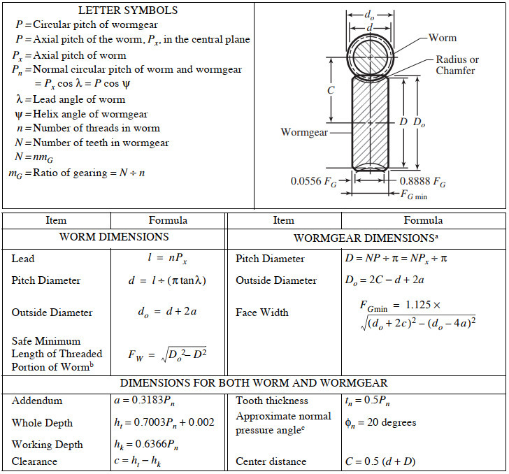
We know that linear velocity of the worm vW l. American Standard Design for Fine-pitch Worm Gearing ANSI B69-1977 This standard is intended as a design procedure for fine-pitch worms and wormgears having axes at right angles. Design the worm gear if it is made of Phosphor bronze 8.
CHAPTER 11 Worm Gears Chapter Outline 111 Introduction 439 112 Force Analysis 446 113 AGMA Equations 449 114 Design Procedure 453 115 Conclusions 455 References 456 Further Reading 456 Nomenclature 457 Abstract Worm and wheel gears are widely used for nonparallel nonintersecting right angle gear drive system applications where a high transmission gearing. DG Pitch circle diameter of the worm gear. Introduction to Gear Design Introduction Albert Einstein once said.
Where n Number of starts of the worm. Provisional spur gear selection procedure for a. In this case the tooth winds around the worm shaft like the thread of a screw.
Design shapes of spur gears 3. The pitch line velocity is ideally up to 30 ms. 111 Introduction A worm gear is a cylindrical helical gear with one or.
By varying design the back drive efficiency can be reduced to zero a in a self-tacking or irreversible gear setf the gear tries to drive the worm internal. Things should be made as simple as possible but no simpler This book is an attempt to apply that principle to gear design by presenting information from a manufacturing point-of-view rather than a theoretical one. P Circular pitch of wormgear P axial pitch of the worm P x in the central plane P x Axial pitch of worm P n Normal circular pitch of worm and wormgear Px cos λ P cos ψ λ Lead angle of worm ψ Helix angle of wormgear.
Also the module of the worm as well as the gear must be equal for a mating worm and gear. Plastic worm gears are suitable for 50 torque of bronze worm gears. We will use the term Pitch P for both the pitch in this tutorial.
Direction of Rotation and Thrust Right Hand NOTE. Running a worm gear set with the gear worm wheel as the input member is corn-monly caUed back driving Back drive effi-ciency of a worm gear set is lower than its forward drive efficiency. It does not cover helical gears used as wormgears.
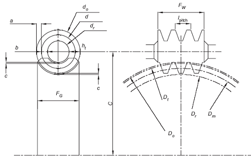
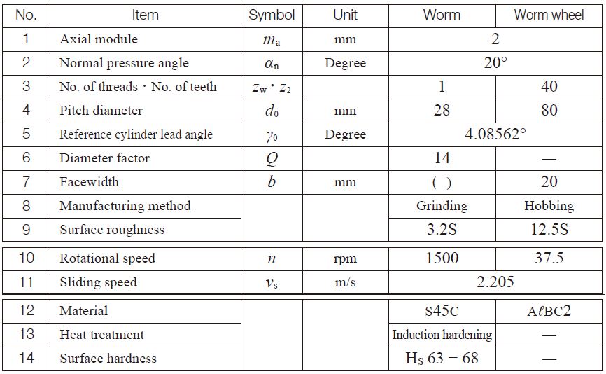
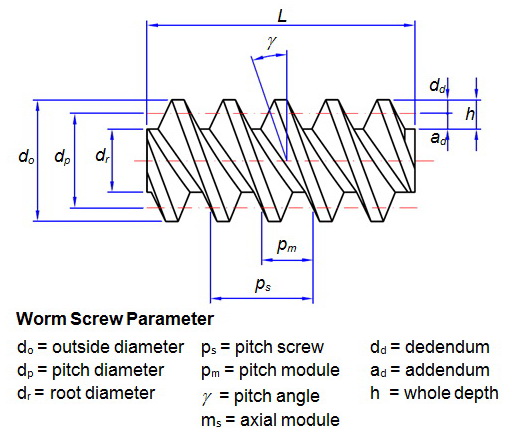
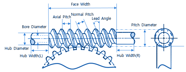
Worm gear design parameters. POM PA 66 Tensile strength R with 23C. Select number of teeth on worm.
Surface Durability Of Worm Gear Khk Gears
Best Worm Gear Design Calculation Pdf

Worm Gear Calculation And Design Mitcalc 12 Youtube
Agma Worm And Spur Gear Design Equations And Calculators

Worm Gear Design Calculation Pdf Merge Peatix

Pdf Machine Design Ii Module 2 Gears Lecture 16 Worm Gears Worked Out Problems Contents Aju Joseph Academia Edu
Worm Gearing Classes Proportions Materials And Worm Gear Cutting
Worm Gears Roy Mech
0 comments
Post a Comment